
With access to Computer Aided Design (CAD) software on the rise, ideas can be quickly and easily modelled by almost anyone, but understanding how that part will be manufactured is very often overlooked. The guide below is intended as a simplified, but valuable building block for designers not wanting to rework their designs, save time and reduce project costs.
Design for Manufacture (DFM) is the process of designing parts, components or products for ease of manufacture with an end goal of making a better product at a lower cost.
In general, DFM is something that should always be at the back of the mind when creating new concepts. The benefits of thinking about these things now far out-weigh the headache of having to address them later. The main reasons designers follow good DFM practice are simple…
- Quicker turnaround
- Reduced cost
- Better quality
Understand your manufacturing method
Traditional manufacturing methods remove material from stock (subtractive manufacturing). That stock is usually in the form of a block, plate or round bar. As a simplified starting point, designers should first consider where their component geometry will fit into the table below and familliarise themselves with the typical machining method.
| Component geometry | Stock material | Process | Typical machining method |
|---|---|---|---|
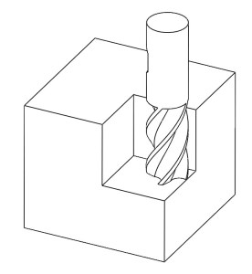
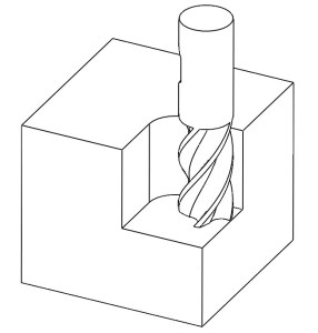
| Thick rectangular or square | Solid block | Mill | A rotating cylindrical cutting tool is moved through a fixed piece of stock material. Spindle axis is generally in the vertical orientation with a minimum of 3-axis of travel (up/down, left/right, backwards/forwards). |
| Cylindrical (shafts, disks, etc) | Round bar | Lathe | Tooling is moved into a fixed piece of rotating stock material. Spindle axis is generally in the horizontal orientation. Cutting tool has 2-axis of travel (left/right, backwards/forwards). |
| Flat, wide and long (2-dimensioinal) | Plate | Laser / Plasma | A hot focused beam is used to melt though the sheet material to create desired shape |
General rules for all machining
- Avoid thin walls. Thin walls add difficulty. Material will want to flex away from the cutting edge of the tool. Vibration may affect surface finish and accuracy will decrease.
- Excessive tolerances. Apply the widest acceptable tolerance to your part. Wide tolerances allow components to be machined faster and cheaper. Tolerances also help to highlight critical areas to the machinist and the person providing the quotation.
- Deep pockets/tall parts. Reduce cost by avoiding the need for long expensive tooling. If depth is important to the function of the design consider introducing progressive steps. Bear in mind that tooling has limited cutting length.
- Deep holes. Assume standard drill lengths to be available in the ratio of 5:1. (Drill diameter x 5 = standard drill depth) Eg. Ø10mm drill will be able to drill a 50mm deep hole, Ø6mm drill = 30mm deep, etc.
- Drill diameters. Drills from 1mm to 10mm commonly step up in 0.1mm increments. Odd sizes outside this rule have to be machined. Wherever possible use standard drill sizes.
- Internal angles with radii. Cylindrical rotating cutting tools can not enter sharp 90° corners without leaving a radius. As a general rule the radius should be a minium of 1/3 of the depth of cut.
- Simple is better. Avoid unnecessary cosmetic features. This includes unnecessary chamfers, radii and engravings. (Remember that you can simply add a note to the drawing asking to “deburr sharp edges”)
- Consider larger orders. Machine set-up is one of the major considerations for job quotation. Cost per part decreases with larger order quantities.
Engineering drawings vs CAD models
There are two routes to receiving a quotation remotely; by providing a drawing and/or by sharing a model.
A lot can be communicated by a simple hand sketch. In fact, until the 1960s this was the only way it was done. Today CAD models are a great communication method. Apart from program specific file types (SolidWorks, Catia, etc) that can only be opened within their native program, an international STandard for Exchange of Product model data exists, known as STEP. The STEP file is an ISO standard format easily shared and viewed by all good CAD software. Simply “Save as” and choose STEP. This way everyone can open and view the model and project timing is not wasted.
Today the need for engineering drawings arises when requesting quotations AND when communicating missing details from the CAD model. This could be, material, threads or tapped hole detail, surface finish, surface treatment, tolerances, etc. Missing CAD detail is important to both the machinist and the person providing the quotation. As a minimum, try to dimension the major size of the part (WxBxH) so that the material volume can be estimated and all important detail not captured in the CAD model.
Conclusion
- Understand your manufacturing method – If possible, decide on your manufacturing method before designing your component and keep it in mind throughout your design process.
- Obey the general rules for machining – keep it simple.
- Communication – Use all the tools available to you to help communicate the important features of your design.

You must be logged in to post a comment.